Lost or Broke Your Roadster Keyed Lugnut?

By Pete Gruber | May 4, 2021 |

BACKSTORY

The Roadsters came from Tesla with 4 locking keys, one on each wheel.  With age, repeated use, and overzealous tire shop techs using impact wrenches (which these were never designed for), the keys eventually break.

When they break, finding a replacement is a real challenge, and removing them without a key, is usually a carbide drilling process, using a tapout, and sometimes damaging the wheel (no longer in production).

The original intent of these anti-theft keyed lug nuts (1 per wheel), was to prevent wheel theft.  We have never heard any Roadster owner complaining about wheel theft, ever.

TYPICAL FAILURE

The worst time for these to fail is when you have a flat tire, need a repair or replacement, and the tire shop suddenly cannot get the wheel off.  A typical failure is the raised keyed portion has cracked or disintegrated from impact wrench use.

SOLUTION

We maintain a library of lugnut keys, donated by the Roadster community, and available to all for free.

Tesla Service Centers used to have lugnut key sets and may be a resource as well.

If you lost your Roadster anti-theft security key, or some tire guy busted up the key by using an impact wrench, and are in a bind trying to get your tires replaced or fixed, we can help.

We will let you borrow the correct key from our growing library of keys.  All we ask is that if you borrow one, you return the one we will send you.

Lotus did not make just one anti-theft key, but a couple of dozen, each one slightly different from the rest.  Look for the letter on the back of the key to identify the one you need and send us good pictured of the key pattern on the stuck lugnut.

Through the generosity of our Roadster customers, who have asked us to replace the anti-theft keyed lug nuts eliminating the need for a key, and donated their old key to our library, we are able to offer this free keyed lug nut service.

Here is how it works:

  • If yours is broken, look on the back for a letter and let us know what it is
  • If it is lost, send us a picture of the anti-theft key pattern (close up recommended)
  • Buy a set of 4 lug nuts to replace the anti-theft keyed version, or a set of 20 new zinc plated to replace all your lug nuts.
  • In either event, we will send you the correct anti-theft removal key from our collection allowing you to remove and replace them.
  • We ask you return the anti-theft key to our collection for the next Roadster owner that needs one

We offer this as a free service to our Roadster community.


The standard issue torx driver that came with the Roadster is soft steel.  With use, we have seen many of them twisted with age.
We offer a lifetime warranty hardened steel Torx Driver Bit for the Roadster lugnuts which will outlast the car.

Roadster – Service Manual
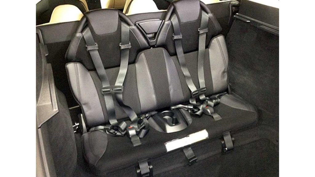
By jessebenedict | March 30, 2021 |

ROADSTER SERVICE MANUAL

MX – Windshield Assembly (Remove and Replace)

By Pete Gruber | June 2, 2020 |

Windshield Assembly (Remove and Replace)

FRT No: 10200102

Special tools required for this procedure:

Supplier Part Number Description
Tesla 1071571-00-B Model X windshield lift tool

Remove

    1. Remove the hood assembly (refer to procedure).
    2. Remove the cowl screen panel (refer to procedure).
    3. Apply painter’s tape to the panels that are adjacent to the windshield.
    4. Remove the LH and RH upper B-pillar trim panels (refer to procedure).
    5. Remove the LH and RH sun visors (refer to procedure).
    6. Remove the screws that secure the front of the headliner to the body (torque 2 Nm).
    1. Release the clips that secure the front of the headliner to the roof and partially lower the headliner.
    2. Disconnect the electrical connectors at the front of the headliner.
    3. Move the harness out of the working area. Secure it with tape, as necessary.
    4. Remove the light/rain sensor (refer to procedure).
    5. Release the overhead console harness assembly from the windshield.
    6. Cut an appropriate length of square wire and insert the wire into the Centerstart tool.
  1. Push the tool through the adhesive near the lower RH corner of the windshield. Puncture both lines of adhesive.
    Caution: Insert the tool on the RH side of the defrost mesh grille to avoid damaging the grille.
  2. Pull the wire through and remove the tool.
  3. Connect the T-handles to the wire.
    Note: Use an assistant for the remainder of the removal steps to make removal easier.
  4. Cut out the windshield.
    Warning: To avoid personal injury, eye protection must be worn when performing this operation.
    Caution: Take care not to damage component(s).
  5. Clean the windshield with glass cleaner and a clean cloth.
  6. Remove the covers from the vacuum cups on the windshield lift tool, then use glass cleaner and a clean cloth to clean the vacuum cups.
Warning: The windshield and vacuum cups must be cleaned with glass cleaner before continuing. Dirt and oil on the windshield or vacuum cups can cause the vacuum cups to lose vacuum, possibly causing the windshield to fall and cause injury.
    1. Position the windshield lift tool over the mount for the forward-facing camera, with the center cup toward the front of the vehicle.
      Warning: Ensure that none of the vacuum cups are positioned over a crack in the windshield. The vacuum cup will not attach securely, possibly causing the windshield to fall and cause injury.
    2. Attach the vacuum cups of the windshield lift tool to the outer surface of the windshield. Pump each vacuum cup until the red line disappears.
  1. If the windshield lift tool is not centered on the windshield, attach vacuum cup handles to the outer surface of the windshield to help guide the windshield when it is removed.
  2. Connect the windshield lift tool to the gantry.
  3. Raise the windshield off of the body, then roll the gantry away from the vehicle.
  4. Place the windshield in a disposal container, on a workbench, on 2 windshield stands, or in another safe storage area.
    Warning: Do not allow the windshield to be supported by the vacuum cups for an extended period of time. The vacuum cups eventually lose vacuum, possibly causing the windshield to fall and cause injury.

Installation

  1. Use the adhesive scraper to remove the excess adhesive from the body.
  2. Clean the remaining adhesive on the body with alcohol wipes. Allow the alcohol to dry fully before continuing to the next step.
  3. Apply primer to the body as directed by the adhesive manufacturer. Ensure that the primer fully covers any nicks or scratches in the paint.
    Warning: Check the expiration date of the primer and adhesive before use.
    Note: Check the primer and adhesive packaging for the appropriate working times for each product. Prepare the necessary tools and work environment so that the the windshield can be installed within the specified working times.
    Note: This procedure requires 2-3 tubes of adhesive.
  4. Clean the etched area of the windshield with alcohol wipes. Allow the alcohol to dry fully before continuing to the next step.
  5. Apply primer to the etched area of the windshield as directed by the adhesive manufacturer.
    Note: Check the primer packaging for the appropriate wait time before applying adhesive.
  6. Attach 2 vacuum cup handles to the outer surface of the windshield, 1 near each lower corner.
  7. Position the windshield lift tool over the mount for the forward-facing camera, with the center cup toward the front of the vehicle.
  8. Attach the vacuum cups of the windshield lift tool to the outer surface of the windshield. Pump each vacuum cup until the red line disappears.

  9. Connect the windshield lift tool to the gantry. Do not lift the windshield yet.
    Warning: Do not allow the windshield to be supported by the vacuum cups for an extended period of time. The vacuum cups eventually lose vacuum, possibly causing the windshield to fall and cause injury.
  10. Cut the applicator tip on the adhesive tube in a triangular pattern: 8 mm wide, 14 mm tall.
  11. Apply the adhesive to the body.
  12. Lift the windshield, and roll the gantry to the vehicle.
Note: The next steps require at least 2 assistants.
  1. Install the windshield. Align the locator posts to the holes in the body.
  2. Ensure that the gaps between the windshield and the body are equal front to back and side to side. Evenly and progressively press the glass onto the spacers.
  3. Clean off any excess adhesive that was extruded from the joint.
    Warning: Do not drive the vehicle until the adhesive has cured. Refer to the adhesive packaging for the safe drive-away time.
  4. Have an assistant use a hose to spray water along the edges of the windshield. Ensure that no water leaks into the interior.
  5. Reinstall the components that were removed for access.

    Note:

MX – Parts Catalog

By Pete Gruber | June 2, 2020 |

Model X Parts Catalog

Parts Categories


MX – Headlight – Adjust – North America

By Pete Gruber | June 2, 2020 |

Headlight – Adjust – North America

FRT No: 17409000

North America (SAE)

    1. Prepare a work area for adjusting the headlights:
      • The area is darkened.
      • The ground is flat and level.
      • There is a wall with a white matte surface.
        Note: The wall should be at least 6 ft (1.8 m) high and 12 ft (3.7 m) wide.
    2. Put a piece of tape on the wall to indicate where the beam should show.
      • Air suspension vehicles: 33.4 in (849 mm) from the ground
      • Coil suspension vehicles: 33.8 in (859 mm) from the ground
    3. Measure 25 ft (7.62 m) away from the wall and put a piece of tape on the ground to indicate where the vehicle should be parked.
    4. Park the vehicle perpendicular to the wall so that the front fasica is flush with the tape that was placed on the ground in the previous step.
    5. Air suspension vehicles: Set the suspension height to “Standard”.
    6. Ensure that all 4 tires are inflated to their recomended settings. Refer to General Information > Technical Data > Tire pressures.
    7. Ensure that the vehicle is level by rocking it from side to side.
    8. Remove the LH and RH underhood aprons (refer to procedure).
  1. Use the touchscreen to turn on the low beam headlights.
  2. Cover the RH headlight; ensure that all light from the right headlight is blocked.
  3. Locate the headlight adjuster.
  4. Adjust the headlight so that the distance between the ground and the top right part of the beam on the wall is:
    • Air suspension vehicles: 33.4 in (849 mm)
    • Coil suspension vehicles: 33.8 in (859 mm)
    Note: Turning the screw clockwise moves the beam upwards. Turning the screw counterclockwise moves the beam downwards.
  5. Repeat steps 10-12 by covering the LH headlight and adjusting the RH headlight.
  6. Reinstall all components that were removed for access.
  7. Use the touchscreen to put the headlight back to “Auto” mode.

MX – Raising and Supporting the Vehicle

By Pete Gruber | June 2, 2020 |

Raising and Supporting the Vehicle

View large image. 

Caution: Do not jack or support the vehicle on any other points than those shown. Failure to comply will result in damage to the body or chassis components.
Caution: If the procedure requires the rear doors or liftgate to be open while the vehicle is raised, closely watch the position of the rear doors or liftgate as the vehicle is being raised to avoid contact with the lift mechanism, ceiling, or objects hanging from the ceiling.

Two post lift

Refer to Service Manual procedure 10000205 for instructions.

Warning: Death, serious injury or damage to the vehicle can occur if the vehicle is improperly lifted on a two post lift.

Four post lift

Refer to Service Manual procedure 10000405 for instructions.

Warning: Death, serious injury or damage to the vehicle can occur if the vehicle is improperly lifted on a four post lift.

Hydraulic jack

A hydraulic jack with a minimum 2500 kg (5500 lb) load capacity must be used.

Warning: For vehicles with air suspension, suspension ‘Jack’ mode must be activated before lifting the vehicle with a hydraulic jack (refer to procedure). Failure to do this might lead to suspension damage and could cause serious personal injury.
Warning: Do not start work on the underside of the vehicle until safety stands have been positioned under the body reinforced pads. Never get under a vehicle that is only supported by a jack.
Warning: Always chock the wheels before lifting the vehicle with a hydraulic jack.

MX – Camera – Forward Facing (Remove and Replace)

By Pete Gruber | June 2, 2020 |

Camera – Forward Facing (Remove and Replace)

FRT No: 17231002

Removal

    1. Remove the rear view mirror (refer to procedure).
    2. Use a trim tool to release the upper camera cover from the windshield bracket.
      Caution: Take care not to damage component(s).
      Note: The following image shows the rear view mirror still installed.
    3. Remove the screws (x4) that secure the camera mounting plate to the windshield bracket.
    1. While supporting the camera and mounting plate, disconnect the electrical connector from the rear of the camera by pulling the gold-colored tab away from the camera.
  1. Release the camera and mounting plate from the vehicle.
  2. Remove the screws (x3) that secure the camera to the mounting plate.
  3. Release the camera from the mounting plate.

Installation

Caution: Do not touch the camera lens at any point during this procedure.
    1. Clean the inside surface of the windshield with glass cleaner and ensure it is fully dry before installing the forward facing camera.
    2. Loosely install the center screw that secures the mounting plate to the camera. Do not torque the screw at this time.
  1. Loosely install the RH screw that secures the mounting plate to the camera. Do not torque the screw at this time.
  2. Loosely install the LH screw that secures the mounting plate to the camera. Do not torque the screw at this time.
  3. Torque the screws (x3) in the order shown (torque 3 Nm).
  4. While supporting the camera and mounting plate, connect the electrical connector to the rear of the camera.
  5. Install the screws (x4) that secure the camera mounting plate to the windshield bracket (torque 3 Nm).
  6. Resecure the upper camera cover to the windshield bracket.
  7. Reinstall the rear view mirror (refer to procedure).
  8. Calibrate the forward facing camera (refer to procedure).

MX – Applique – Spine – Center (Remove and Replace)

By Pete Gruber | June 2, 2020 |

Applique – Spine – Center (Remove and Replace)

FRT No: 10403002

Removal

  1. On both sides of the vehicle, remove the rear door upper glass (refer to procedure).
  2. Place suitable protective covers on the 2nd row seats.
Note: While performing the rest of this procedure, stand on the 2nd row seats and work through the upper glass window hole.
  1. Remove the seal in front of the center applique.
Note: The remainder of this procedure requires an assistant.
  1. Starting at the front of the vehicle, use a cutting wire to cut the sealant underneath the perimeter of the center applique as much as possible.
    Note: The applique has clips that prevent using the wire to cut all of the sealant.

    View large image. 

  2. Starting at the front of the vehicle, use a cutting blade to cut through the remainder of the sealant.
    Tip: Use glass cleaner or a similar lubricant to aid in cutting.

    View large image. 

    Tip: While cutting, have an assistant pull up on the applique.

    View large image. 

Installation

Installation procedure is the reverse of removal, except for the following:

  • Remove all excess sealant.
  • Install the weatherstrip on the center applique.
  • Apply primer to the perimeter of the applique, as directed by the adhesive manufacturer.

    View large image. 

    Warning: Check the expiration date of the primer and adhesive before use.
    Note: Check the primer and adhesive packaging for the appropriate working times for each product. Prepare the necessary tools and work environment so that the the applique can be installed within the specified working times.
    Note: Check the primer packaging for the appropriate wait time before applying adhesive.

MX – Sensor – Ultrasonic – Rear Door – LH

By Pete Gruber | June 2, 2020 |

Sensor – Ultrasonic – Rear Door – LH (Remove and Replace)

FRT No: 11334202

Special tools required for this procedure:

Supplier Part Number Description
1080580-00-A Heat gun
1080603-00-A Infrared thermometer
1080978-00-A Force gauge
1080978-10-A 22 mm diameter tip for force gauge

Removal

  1. Open the LH front door. Open the LH rear door to a comfortable working position.
  2. Ensure that the LH rear window is fully closed.
  3. Remove the rear door closeout panel (refer to procedure).
  4. Disconnect the electrical connector from the ultrasonic sensor.
  5. Twist the cap clockwise to remove it.
    Note: When the cap is removed, the spacer and spring might fall out of the sensor carrier.
    1 Cap
    2 Spring
    3 Spacer
    4 Ultrasonic sensor
    5 Carrier
    6 Butyl patch
  6. Remove the spacer and spring.
  7. Remove the ultrasonic sensor from the carrier.
    Note: Inspect the face of the sensor; ensure that the adhesive that affixed the sensor to the door was removed with the sensor. If the adhesive remains stuck to the door, use a plastic trim tool to remove it.
  8. Discard the ultrasonic sensor.

Installation

Caution: The ultrasonic sensor is a one time use component. If the ultrasonic sensor is removed, a new ultrasonic sensor must be installed.
    1. Attach the 22 mm tip to the force gauge.
    2. Connect the electrical connector to a new ultrasonic sensor.
    3. Ensure that there is sufficient slack in the electrical harness to prevent it from pulling on the sensor when it is installed. Reposition the harness as necessary.
  1. Use alcohol wipes to clean the sensor mounting area on the door panel.
Caution: The ultrasonic sensor and door panel must be at an elevated temperature for proper adhesion. Read this section fully before continuing. Perform steps 5-10 without stopping.
  1. Use an infrared thermometer to check the temperature of the door panel. If necessary, use the heat gun to heat the door panel to at least 25 degrees C (77 degrees F).
    Caution: Do not continue this procedure unless the door panel is at least 25 degrees C (77 degrees F).
  2. Use a spring clamp, bar clamp, or similar tool to gently hold the sensor with the coupling tape facing up.
  3. Aim the infrared thermometer at the face of the ultrasonic sensor. Use the heat gun to heat the face of the ultrasonic sensor to 45 degrees C (113 degrees F).
    Warning: Wear heat-resistant gloves when performing this operation.
  4. Remove the protective film from the coupling tape on the new sensor.
  5. Install the ultrasonic sensor.
  6. Use the force gauge to apply a force of 55 N to the sensor for at least 10 seconds.
  7. Reinstall all components that were removed for access.
    Note: When reinstalling the spacer, ensure that the flat side faces the sensor.

MX – 2nd Row Seat Removal

By Pete Gruber | June 2, 2020 |

Seat Assembly – 2nd Row – LH (Remove and Install)

FRT No: 13050101

Note: If the seat is unable to move fully forward and backward, it is not possible to remove all fasteners that secure the seat. Refer to Seat Assembly – 2nd Row – LH (With Broken Seat Track Motor) (Remove and Install).

Remove

    1. Remove the 2nd row middle floor panel (refer to procedure).
    2. Move the 2nd row seats to their forwardmost position.
    3. Pull outward on the outboard LH podium trim to release the clips that secure it to the seat.
      Caution: Replace any broken clips.
    4. Move the RH 2nd row seat to the Easy Entry position.
    5. Working from the RH side of the vehicle, pull outward on the inboard LH podium trim to release the clips that secure it to the seat.
    6. Using a pick or similar tool, remove the carpet at the base of the LH seat forward to access the screws underneath.
      Note: This carpet is a one time use component. Ensure that a new carpet is installed during reinstallation.
  1. Release the screws (x2) that secure the front sliding panel to the seat tracks (torque 2.5 Nm).
  2. Release the sliding panel from the seat tracks.
  3. Move the LH 2nd row seats to the Easy Entry position.
  4. Remove the bolts (x6) that secure the rear of the seat tracks.
  5. Move the 2nd row seats to their rearmost position.
  6. Release the fasteners that secure the LH outboard support bracket (torque 2.5 Nm).
  7. Remove the rocker duct.
  8. Remove and discard the bolts (x8) that secure the front of the seat tracks.
  9. Disconnect 12V power (refer to procedure).
Warning: Wait at least 2 minutes before continuing to allow the airbag circuits to fully discharge.
    1. Release the clip that secures the harnesses to the bracket in front of the seat.
    2. Working from the bottom of the harness block, use a pick or similar tool to release the locking tabs to disconnect the small yellow and gray harnesseses.
  1. Working from the top of the harness block, disconnect the large black harness.
  2. Prepare a padded surface for the seat when it is removed in the next step.
  3. With an assistant, carefully remove the seat from the vehicle and place it on the padded surface with the outboard side of the seat facing up.

Installation

Warning: Ensure that 12V is still disconnected.
  1. Position the seat in the vehicle.
  2. Reconnect the seat harnesses.
  3. Reconnect 12V power.
  4. With Toolbox running, re-enter Seat Install Mode.
  5. Reinstall bolts for the rear of the seat in the following order. If any threads are damaged, discard the fastener and use a rivnut.
    • Bolts 1-4: 33 Nm
    • Bolts 5 & 6: 22 Nm
  6. Install new bolts for the front of the seat in the following order (torque 33 Nm):
  7. In the Toolbox Seat Install panel, run the Seat Calibration program.
  8. Install a new carpet at the base of the seat.
  9. Reinstall all components that were removed for access.

MX – Annual Service

By Pete Gruber | June 2, 2020 |

Annual Service

FRT No: 00019905

Note: Not all of the procedures listed here need to be performed at each Annual Service. Refer to SC-15-00-001 for a list of the required procedures to perform at the relevant service interval.

Check for Alerts, Repair any Issues Found, Clear Alerts

  1. Connect a laptop with Toolbox to the vehicle.
  2. Check for active alerts and DTCs.
  3. After performing any necessary repairs, clear any alerts and DTCs.

Wiper Blades

Replace the wiper blades (refer to procedure).

Cabin Air Filter

Replace the particulate filter (refer to procedure).

Coolant

Drain and refill the cooling system (refer to procedure).

Steering Gear Bolts

Ensure that the bolts that secure the steering rack to the subframe are fully torqued:

Hood Release Latch

Apply approximately 0.1 grams of RheoGel TEK676 grease to both of the areas shown.

Front latch Rear latch

A/C Desiccant Bag

Replace the desiccant bag (refer to procedure).

Brake Fluid

Perform the full system bleed procedure (refer to procedure).

Brake Caliper Pad Slides

Note: This is recommended for cold weather regions.
Note: Cleaning and lubricating the caliper pad slides/abutments is not included in the Annual Service price.
Note: Perform the following steps on all 4 calipers.
  1. Remove the pad retaining pins and collect the anti-rattle spring.
    Note: Always check that the anti-rattle clip has not been damaged. This part is easily damaged and is important to help eliminate squeaks.
    Front caliper Rear caliper
  2. Use a suitable tool to gently push the pistons back into caliper.
  3. Remove the brake pads from the caliper.
  4. Thoroughly clean the caliper pad slides and abutments with a hand brush (1057223-00-A) and soapy water.
    Caution: If there is rust or pitting on the caliper that cannot be removed with a hand brush, replace the caliper.

  5. Apply an even layer of Silaramic lubricant (1063021-00-A) to the caliper pad slides. Remove any excess lubricant.
  6. Apply an even layer of copper paste between the shim and the backing plate. Remove any paste that squeezes out after installing the shim.
    Caution: Ensure that the brake pads move freely.
    Caution: Do not apply copper paste to the caliper, seals, or any component other than the shim and backing plate.

Transmission Fluid

Drain and refill the fluid from the gearboxes:

  • Non-Performance vehicles:
  • Performance vehicles:
    • Drain and refill the fluid from the front drive unit (refer to procedure).
    • Drain and refill the fluid from the large rear drive unit .(refer to procedure)

Thermal System Test

  1. Connect a laptop with Toolbox to the vehicle.
  2. Run the Thermal System Test and follow any onscreen instructions.

Suspension Fasteners

  1. Check the torque of the front suspension bolts (refer to procedure).
  2. Check the torque of the rear suspension bolts (refer to procedure).

Wheel Alignment Check

Perform a wheel alignment check (refer to procedure).

Wheel Alignment Adjustment

Note: This is recommended if the wheel alignment check determines the wheel alignment is out of specification.
Note: Wheel alignment adjustment is not included in the Annual Service price.

Perform a wheel alignment adjustment (refer to procedure).

MX – Changing the 12 Volt Battery

By Pete Gruber | May 27, 2020 |

Battery – Auxiliary – 12V (Remove and Replace)

FRT No: 17011202

Removal

  1. Disconnect 12V power (refer to procedure).
  2. Release the red plastic cover from the 12V positive connection.
  3. Disconnect the 12V battery positive connection (torque 10 Nm).
  4. Release the edge clip and the barrel clip that secure the 12V harnesses from the top of the battery cage.
  5. Release the edge clip that secures the coolant hose to the bottom of the battery cage.
  6. Release the battery vent tube by gently pulling it way from the 12V battery.
    Note: The following image shows the 12V battery ground connection still connected.
  7. Remove the lower bolts (x2) that secure the battery cage to the plastic support beam (torque 6 Nm).
    Note: Components have been removed in this graphic to aid clarity.
  8. Remove the upper bolts (x2) that secure the battery cage to the crossmember (torque 15 Nm).
    Note: Components have been removed in this graphic to aid clarity.
  9. Remove the battery and battery cage assembly from the vehicle and set it on a flat surface.
  10. Remove the nut that secures the battery hold down bracket to the battery cage (torque 4 Nm). Remove the battery hold down bracket.
  11. Lift the 12V battery straight up to remove it from the battery cage.

Installation

Installation procedure is the reverse of removal.

MS – Paint Codes

By Pete Gruber | May 26, 2020 |

Vehicle paint codes

The vehicle paint code is printed in the lower left hand corner of the manufacturing certification label. This label is affixed to the driver’s side door jamb, except for vehicles in China, where it is affixed to the passenger’s side door jamb.

Paint Code Paint Color Finish
PBCW Base White Solid
PBSB Black Solid
PMAB Brown (2012-2014) Metallic
PMMB Blue (2012-2015) Metallic
PPSB Blue (2015 and later) Metallic
PMSG Green (2012-2014) Metallic
PMTG Gray (2012-2014) Metallic
PMNG Gray (2014 and later) Metallic
PMSS Silver (2012-2015) Metallic
PPTI Titanium Silver (2015 and later) Metallic
PPSR Signature Red Tricoat Metallic
PPSW Pearl White Tricoat Metallic
PPMR Base Red Tricoat Metallic

MS – Headlight – Adjust – Europe

By Pete Gruber | May 26, 2020 |

Headlight – Adjust – Europe

FRT No: 17400100

Europe (ECE)

  1. Position the vehicle for adjusting the headlights:
    • The vehicle is in a darkened area.
    • The vehicle is on a level surface.
    • The vehicle is perpendicular to a wall that has a white matte surface. The wall must be at least 1.8m (6 ft) high and 3.7 m (12 ft) wide.
    • The headlights are 10 m (32.8 ft) away from the wall.
  2. Ensure that all 4 tires are inflated to their recomended settings. Refer to General Information > Technical Data > Tire pressures.
  3. If the vehicle is equipped with air suspension, set the suspension height to standard.
  4. Ensure that the vehicle is level by rocking it from side to side.
  5. Remove the LH and RH underhood aprons (refer to procedure).
Note: The remainder of this procedure must be performed with someone in the driver seat who weighs at least 75 kg (166 lbs).
  1. Note the height between the ground and the center projecter lens on the driver side headlight.
  2. Mark a straight line between each of the center projector lenses and the wall. At the point where each line meets the wall, mark the height that was noted in the previous step.
  3. Turn on the low beam headlights.
    Note: For LHD vehicles, the left half the beam is flat, and the right half of the beam angles upward. For RHD vehicles, the right half of the beam is flat, and the left half of the beam angles upward.
  4. Cover the RH headlight; ensure that all light from the RH headlight is blocked.
  5. Locate the 2 adjusters on the LH headlight.
  6. Adjust the headlight horizontally so that the top of the flat part of the beam is 100 mm below the height that was noted in step 6.
  7. Adjust the headlight vertically so that the beam begins to angle upward at the line that was marked in step 7.
  8. Repeat steps 9-12 to adjust the RH headlight.

MS – VIN Decoder

By Pete Gruber | May 26, 2020 |

Vehicle Identification Number (VIN)

VIN Locations

The Vehicle Identification Number (VIN) is visible in 3 locations:

The bottom corner of the driver’s side of the windshield On the driver’s side door jamb Vehicles built before September 2015: On the front crossmember, beneath the rear center underhood apron Vehicles built after September 2015: On the RH sill panel
Note: The above images of the VIN location on the windshield and door jamb show LHD vehicles. The locations are mirrored on RHD vehicles.
Note: Model S in China have the VIN located on the passenger’s side door jamb instead of the driver’s side.
Note: When corresponding with Tesla, always include the VIN (and the drive unit serial number, if necessary).

2012-2016 VIN Decoders

Digits 1-3

World Manufacturing Identifier
5YJ = Tesla

Digit 4

Series Name
S = Model S

Digit 5

2012/2013: Body Type 2014/2015: Body Type 2015/2016: Body Type
A = 5 door Hatchback LHD RWD A = Hatchback 5 door / LHD A = Hatchback/5-DR LHD
B = 5 door Hatchback LHD AWD B = Hatchback 5 door / RHD B = Hatchback/5-DR RHD
C = 5 door Hatchback RHD RWD
D = 5 door Hatchback RHD AWD

Digit 6

2012/2013: Restraint Systems 2014: Restraint Systems 2015: Restraint Systems 2015/2016: Restraint Systems
1 = manual Type 2 USA seat belts, dual front airbags, front/rear side airbags, knee airbags 1 = Type 2 manual seatbelts (FR, SR*3) with front airbags, PODS, side inflatable restraints, knee airbags (FR) 1 = Type 2 manual seatbelts (FR, SR*3) with front airbags, PODS, side inflatable restraints, knee airbags (FR) 1 = Type 2 manual seatbelts (FR, SR*3) with front airbags, PODS, side inflatable restraints, knee airbags (FR)
2 = manual Type 2 EU seat belts, dual front airbags, front/rear side airbags, knee airbags 2 = Type 2 manual seatbelts (FR, SR*3) with front airbags, side inflatable restraints, knee airbags (FR)
3 = Type 2 manual seatbelts (FR, SR*3) with front airbags, side inflatable restraints 3 = Type 2 manual seatbelts (FR, SR*3) with front airbags, side inflatable restraints 3 = Type 2 manual seatbelts (FR, SR*3) with front airbags, side inflatable restraints
4 = Type 2 manual seatbelts (FR, SR*2) with front airbags, side inflatable restraints, knee airbags (FR)
5 = Type 2 manual seatbelts (FR, SR*2) with front airbags, side inflatable restraints
6 = Type 2 manual seatbelts (FR, SR*3) with front airbags, side inflatable restraints 6 = Type 2 manual seatbelts (FR, SR*3) with front airbags, side inflatable restraints
7 = Type 2 manual seatbelts (FR, SR*3) with front airbags, side inflatable restraints & active hood 7 = Type 2 manual seatbelts (FR, SR*3) with front airbags, side inflatable restraints & active hood 7 = Type 2 manual seatbelts (FR, SR*3) with front airbags, side inflatable restraints & active hood
8 = Type 2 manual seatbelts (FR, SR*2) with front airbags, side inflatable restraints & active hood 8 = Type 2 manual seatbelts (FR, SR*2) with front airbags, side inflatable restraints & active hood

Digit 7

2012/2013: Charger Type 2014/2015: Battery Type 2015: Battery Type 2015/2016: Fuel Type
A = 10 kW Charger H = Lithium-Ion Battery – High Capacity S = Lithium-Ion Battery – Standard Capacity E = Electric
B = 20 kW Charger S = Lithium-Ion Battery – Standard Capacity H = Lithium-Ion Battery – High Capacity
C = 10 kW Charger, w/ DC fast charge V = Lithium-Ion Battery – Ultra High Capacity
D = 20 kW Charger, w/ DC fast charge

Digit 8

2012/2013: Motor / Drive Unit & Battery Type 2014: Motor Drive Unit 2015/2016: Motor/Drive Unit Type
C = Base A/C Motor, Tier 2 battery (31-40 kWh) 1 = Single Motor – Three Phase A/C Induction 1 = Single Motor -Three Phase A/C Induction – Large Base
G = Base A/C Motor, Tier 4 battery (51-60 kWh) 2 = Dual Motors -Three Phase A/C Induction 2 = Dual Motors -Three Phase A/C Induction – Small Base + Small Base
N = Base A/C Motor, Tier 7 battery (81-90 kWh) 3 = Single Motor -Three Phase A/C Induction – Large Performance
P = Performance A/C Motor, Tier 7 battery (81-90 kWh) 4 = Dual Motors -Three Phase A/C Induction – Small Base + Large Performance

Digit 9

The 9th digit is a check digit. A check digit is the result of a mathematical formula based on all other digits in the VIN. It is designed to lower the likelihood of errors and fraud. All vehicles produced in North America are required to have a check digit as the 9th digit of the VIN.

Check Digit
?

Digit 10

2012/2013: Model Year 2014: Model Year 2015: Model Year 2016: Model Year
C = 2012 E = 2014 F = 2015 G = 2016
D = 2013

Digit 11

Plant of Manufacture
F = Fremont, CA, USA

Digits 12-17

2012-2014

2012-2014: Production Sequence
A = Alpha Prototype
B = Beta Prototype
F = Founder Series
P = Production
R = Release Candidate
S = Signature Series

Tesla uses sequential numbers starting with 00001 to represent the production sequence of the vehicle. The production sequence numbering does not start at 00001 with each new model year.

2015/2016

For the following prototype and special series vehicle builds, Tesla uses sequential numbers in digits 13-17, starting with 00001 and ending with 99999.

2015: Production type
A = Alpha Prototype
B = Beta Prototype
R = Release Candidate
S = Signature Series

For normal production vehicles, Tesla uses sequential numbers in digits 12-17, starting with 000001 and ending with 999999.

MS – Headlight – Adjust – North America

By Pete Gruber | May 26, 2020 |

Headlight – Adjust – North America

FRT No: 17400000

North America (SAE)

  1. Prepare a work area for adjusting the headlights:
    • The area is darkened.
    • The ground is flat and level.
    • There is a wall with a white matte surface.
      Note: The wall should be at least 6 ft (1.8 m) high and 12 ft (3.7 m) wide.
  2. Put a piece of tape on the wall 27.5 in (698 mm) from the ground to indicate where the beam should show.
  3. Measure 25 ft (7.62 m) away from the wall and put a piece of tape on the ground to indicate where the vehicle should be parked.
  4. Park the vehicle perpendicular to the wall so that the front fasica is flush with the tape that was placed on the ground in the previous step.
  5. Air suspension vehicles: Set the suspension height to “Standard”.
  6. Ensure that all 4 tires are inflated to their recomended settings. Refer to General Information > Technical Data > Tire pressures.
  7. Ensure that the vehicle is level by rocking it from side to side.
  8. Remove the LH and RH underhood aprons (refer to procedure).
  9. Use the touchscreen to turn on the low beam headlights.
  10. Cover the RH headlight; ensure that all light from the right headlight is blocked.
  11. Locate the headlight adjuster.
  12. Adjust the headlight so that the distance between the ground and the top right part of the beam on the wall is 27.5 in (698 mm).
  13. Repeat steps 10-12 by covering the LH headlight and adjusting the RH headlight.
  14. Reinstall all components that were removed for access.
  15. Use the touchscreen to put the headlight back to “Auto” mode.

MS – 3rd Row Seat Removal

By Pete Gruber | May 26, 2020 |

Seat Assembly – 3rd Row (Remove and Replace)

FRT No: 13028002

Removal

  1. Open the liftgate.
  2. Fold down the third row seats.
 Caution: Take care not to damage component(s).
 Caution: Protect the interior trim from possible damage.
  1. Remove the bolts that secure the third row seatbelt straps (torque 26 Nm). Remove the seatbelt straps.
    Note: The bolts screw into nut inserts that are able to slide freely within the body panel. After removing each seatbelt strap, place a wedge through the bolt hole so that the nut inserts do not slide out of position. If they do, refer to the installation instructions for how to reposition them.
  2. Release the seat cushion catches on either side of the seat assembly.
  3. With an assistant, remove the 3rd row seat from the vehicle.

Installation

Installation procedure is the reverse of removal, except for the following:

  • Before installing the mounting bolts, ensure that the mounting bracket holes are aligned with the threaded nut inserts behind the body panel. If the nut insert does not align with the bolt hole:
    1. Remove the rear sill trim panel (refer to procedure).
    2. Slide the nut insert into position.
  • Verify that the third row seat has full range of motion and latches properly:
    • Ensure that the side latches are engaging correctly into the LH and RH strikers. If the latches are aligned too high, the trunk floor carpet is keeping the seat from sitting in the proper position. Kneel on both sides of the seat cushion, using your body weight to compress the seat and carpet. The carpet should stay compressed, keeping the hooks in proper alignment permanently.
    • Ensure that the upper latch on the 3rd row seat click smoothly into place and is securely fastened to the 2nd row seatback.
      1. Remove the 3 screws on the back of the latch trim cover.
      2. Lift the handle cover. Remove the latch trim cover to expose the 4 retaining nuts.
      3. Loosen the 4 nuts slightly, so that the latch assembly is free to move up and down for adjustment.
      4. With the 3rd row seatback latched to the 2nd row seat, center the latch position free play. The latch assembly will self-align to the 2nd row seat striker.
      5. Tighten the 4 latch nuts (torque 5 Nm).
      6. Unlatch the 3rd row seat. Reinstall the latch surround trim piece and secure it with the 3 screws (torque 0.5 Nm).
      7. Verify proper latching of the 3rd row seat to the 2nd row seat back for smooth engaging and release.

MS – Wheel Alignment Specifications

By Pete Gruber | May 26, 2020 |

Wheel Alignment

Table 1. Air Suspension (excluding Dual Motor All Wheel Drive)
 Location Front Rear
 Camber -0.75 +/- 0.45 -1.75 +/- 1.00
 Camber Split 0.00 +/- 0.30 Not applicable
Caster 4.00 +/- 0.50 Not applicable
 Caster Split 0.00 +/- 0.20 Not applicable
 Single Wheel Toe Out 0.05 (In 0.10 to Out 0.20) In 0.20 (In 0.05 to In 0.35)
 Total Toe Out 0.10 +/- 0.30 In 0.40 +/- 0.30
 Toe Split Not applicable 0.00 +/- 0.20
 Suspension Bolt Height 213.5 +/-5 mm 144 +/- 5 mm (151 +/- 5 mm for Performance Plus Suspension)
Track Width (at wheel center height) 1662 (ref) 1698 (ref)
Wheelbase ———————— 2960 mm (ref)———————
Table 2. Coil Suspension (excluding Dual Motor All Wheel Drive)
Location Front Rear
Camber -0.53 +/- 0.45 -1.25 +/- 1.00
Camber Split 0.00 +/- 0.30 Not applicable
Caster 3.70 +/- 0.50 Not applicable
Caster Split 0.00 +/- 0.20 Not applicable
Single Wheel Toe In 0.02 (In 0.17 to Out 0.13) In 0.19 (In 0.04 to In 0.34)
Total Toe In 0.04 +/- 0.30 In 0.38 +/- 0.30
Toe Split Not applicable 0.00 +/- 0.20
Suspension Bolt Height 230.0 mm (ref) 158 mm (ref)
Track Width (at wheel center height) 1662 mm (ref) 1698 mm (ref)
Wheelbase ————————-2960 mm (ref)———————
Table 3. Air Suspension (Dual Motor All Wheel Drive)
Location Front Rear
Camber -0.75 +/- 0.45 -1.75 +/- 1.00
Camber Split 0.00 +/- 0.30 Not applicable
Caster 4.00 +/- 0.50 Not applicable
Caster Split 0.00 +/- 0.20 Not applicable
Single Wheel Toe Out 0.05 (In 0.10 to Out 0.20) In 0.20 (In 0.05 to In 0.35)
Total Toe Out 0.10 +/- 0.30 In 0.40 +/- 0.30
Toe Split Not applicable 0.00 +/- 0.20
Suspension Bolt Height (at design) 213.5 +/-5 mm 144 +/- 5 mm with 245 mm front and rear tires (151 +/- 5 mm with 245 mm front, 265 mm rear tires)
Track Width (at wheel center height) 1662 mm (ref) 1698 mm (ref)
Wheelbase ———————— 2960 mm (ref)———————
Table 4. Coil Suspension (Dual Motor All Wheel Drive)
Location Front Rear
Camber -0.70 +/- 0.45 -1.25 +/- 1.00
Camber Split 0.00 +/- 0.30 Not applicable
Caster 3.90 +/- 0.50 Not applicable
Caster Split 0.00 +/- 0.20 Not applicable
Single Wheel Toe Out 0.02 (In 0.13 to Out 0.17) In 0.19 (In 0.04 to In 0.34)
Total Toe Out 0.04 +/- 0.30 In 0.38 +/- 0.30
Toe Split Not applicable 0.00 +/- 0.20
Suspension Bolt Height (at design) 217 mm (ref) 158 mm (ref)
Track Width (at contact patch) 1662 (ref) 1698 (ref)
Wheelbase ————————-2960 mm (ref)———————

MS – Changing RWD Battery

By Pete Gruber | May 26, 2020 |

Battery – Auxiliary – 12V (RWD) (Remove and Replace)

FRT No: 17011002

Warning: If the 12V power supply is disconnected, do not attempt to open any doors with door glass in closed position. Failure to follow this instruction could result in door glass shatter.
Note: Before disconnecting the 12V power supply, ensure that the driver’s door window is fully open. Failure to follow this instruction could result in vehicle lockout.

Removal

  1. Disconnect 12V power.
  2. Remove the pollen filter rear housing:
    1. If equipped, release the 2 barrel clips that secure the HV harness to the bulkhead.
    2. Loosen the top right nut that secures the pollen filter rear housing to the bulkhead (torque 6 Nm).
      Note: It is not necessary to completely remove the nut; the tab on the housing is notched.
    3. Remove the remaining nuts (x3) that secure the pollen filter rear housing to the bulkhead (torque 6 Nm).
      Note: The 2 lower nuts secure the HVAC intake drain diverter.
  3. Disconnect the negative battery connection. Lay the negative cable to the side of the battery.
  4. Unplug the first responder’s loop (Do Not Cut!). Wait at least two minutes for all electrical circuits to fully discharge. Failure to unplug the first responder’s loop will void your 12V battery warranty!
  5. Release the lugs (x4) that secure the battery fuse box cover. Remove the cover.
  6. Remove the nut that secures the body harness connector to the battery fuse box (torque 6 Nm).
  7. Remove the nut that secures the battery positive terminal to the fuse box (torque 12 Nm).
  8. Remove the nut that secures the battery fuse box to the battery strap. Tie the battery fuse box aside (torque 6 Nm).
  9. Remove the nuts (x2) that secure the battery strap (torque 3.5 Nm). Remove the strap.
  10. Carefully lift the battery, turn it counter clockwise 90°, and remove it through the opening.
    Note: It can be difficult to remove C&D brand batteries because they do not have handles. It might be helpful to use duct tape in order to lift the battery high enough so that it can be supported from the bottom:
    1. Cut a piece of high-strength duct tape, approximately 18 in (45 cm) in length.
    2. Attach the ends of the duct tape to the long sides of the battery, leaving a large section of duct tape free above the battery. Twist this section of the duct tape back onto itself in order to form a handle.
    3. Using the handle, slowly lift the battery until it can be supported from the bottom.
      Warning: Do not use the handle to fully lift the battery out of the vehicle. Only lift the battery high enough so that it can be supported from the bottom.

Installation

Installation procedure is the reverse of removal, except for the following:
  1. Ensure the first responder’s loop is connected before the 12V battery negative connection! This ensures the high voltage system provides 12V power to the 12V battery as soon as the 12V battery is installed. Not doing so will cause the 12V battery to discharge below a point where the high voltage system will provide 12V power and void your 12V battery warranty.
  2. Ensure that the HVAC intake drain diverter is positioned properly when reinstalling the pollen filter front housing.
     Caution: Take care not to damage component(s).
  3. If changing from an Exide to a C&D battery, update the vehicle’s configuration with Toolbox.
    1. Connect a laptop with Toolbox to the vehicle.
    2. Select Views > Vehicle Configuration > Vehicle Configuration Update.
    3. In the “12V Battery Type” menu, select C&D.

MS – Annual Service

By Pete Gruber | May 26, 2020 |

Annual Service

FRT No: 00019905

Note: Not all of the procedures listed here need to be performed at each Annual Service. Refer to SC-15-00-001 for a list of the procedures to perform at the relevant service interval.

Check for Alerts, Repair any Issues Found, Clear Alerts

  1. Connect a laptop with Toolbox to the vehicle.
  2. In Toolbox, select Perspectives > Predefined Perspectives > Service Default.
  3. Check the Currently Active Alerts, Alert History, and DTCs panels.
  4. After performing any necessary repairs, clear any DTCs:
    1. In the DTCs panel, select the “Clear DTC” radio button.
    2. Click the Start/Play button.

Panoramic Roof

  1. Fully open the sliding glass.
  2. Use compressed air to blow out the drain hoses.
     Caution: Do not exceed 25 PSI (1.7 Bar).
  3. Wrap a clean cloth around a plastic pry tool or other thin tool, then use it to remove dirt and old grease from the 4 channels on each side of the panoramic roof.
  4. Apply Klübersynth noise reduction grease to the 4 channels.
     Caution: Use only Klübersynth noise reduction grease, Tesla part number 1031102-00-A. Other greases can permanently damage the roof seals.
  5. Move the sliding glass to the 30% open position.
  6. Remove the sliding glass (refer to procedure).
  7. Apply Klübersynth noise reduction grease to the sections of the tracks that were blocked by the sliding glass.
  8. Visually inspect the links and shoes for damage.
  9. Reinstall the sliding glass.
  10. Calibrate the panoramic roof (refer to procedure).
  11. Use alcohol wipes to remove any grease from the glass and appliques. Use a clean, dry cloth to remove grease from the rubber seals.
     Caution: Do not use alcohol to remove grease from rubber seals. Alcohol degrades the rubber seals.

Wiper Blades

Replace the wiper blades (refer to procedure).

Cabin Air Filter

Replace the particulate filter (refer to procedure).

Coolant

Drain and refill the cooling system (refer to procedure).

Steering Gear Bolts

Ensure that the bolts (x2) that secure the steering rack to the subframe are torqued to 175 Nm.

Note: Components have been removed in this graphic to aid clarity.

Hood Release Latch

RWD vehicles: Clean the secondary latch, then apply the proper lubricant (refer to procedure).

Dual Motor vehicles: Clean the latch, then apply the proper lubricant (refer to procedure).

A/C Desiccant Bag

Replace the desiccant bag (refer to procedure).

Brake Fluid

Perform the full system bleed procedure (refer to procedure).

Brake Caliper Pad Slides

Note: This is recommended for cold weather regions.
Note: Cleaning and lubricating the caliper pad slides/abutments is not included in the Annual Service price.
Note: Perform the following steps on all 4 calipers.
  1. Remove the pad retaining pins and collect the anti-rattle spring.
    Note: Always check that the anti-rattle clip has not been damaged. This part is easily damaged and is important to help eliminate squeaks.
    Front caliper Rear caliper
  2. Use a suitable tool to gently push the pistons back into caliper.
  3. Remove the brake pads from the caliper.
  4. Thoroughly clean the caliper pad slides and abutments with a hand brush (1057223-00-A) and soapy water.

     Caution: If there is rust or pitting on the caliper that cannot be removed with a hand brush, replace the caliper.

  5. Apply an even layer of Silaramic lubricant (1063021-00-A) to the caliper pad slides. Remove any excess lubricant.
  6. Apply an even layer of copper paste between the shim and the backing plate. Remove any paste that squeezes out after installing the shim.
     Caution: Ensure that the brake pads move freely.
     Caution: Do not apply copper paste to the caliper, seals, or any component other than the shim and backing plate.

Transmission Fluid

Drain and refill the fluid from the gearbox(es):

Tire Rotation

  1. Refer to the recommended tire rotation pattern for the vehicle.
  2. Remove the wheels and reinstall them in the appropriate positions (refer to procedure).

Thermal System Test

  1. Connect a laptop with Toolbox 2.0 or later to the vehicle.
  2. Navigate to Panels > Thermal > Thermal System Test.
  3. Click the Start/Play button.
  4. Follow the onscreen instructions.

Suspension Fasteners

  1. Check the torque of the front suspension bolts (refer to procedure).
  2. Check the torque of the rear suspension bolts (refer to procedure).

Wheel Alignment Check

Perform a wheel alignment check (refer to procedure).

Wheel Alignment Adjustment

Note: This is recommended if the wheel alignment check determines the wheel alignment is out of specification.
Note: Wheel alignment adjustment is not included in the Annual Service price.

Perform a wheel alignment adjustment (refer to procedure).

MS – Changing AWD Battery

By Pete Gruber | May 26, 2020 |

Battery – Auxiliary – 12V (Dual Motor) AWD (Remove and Replace)

FRT No: 17011202

Warning: If the 12V power supply is disconnected, do not attempt to open any doors with door glass in closed position. Failure to follow this instruction could result in door glass shatter.
Note: Before disconnecting the 12V power supply, ensure that the driver’s door window is fully open. Failure to follow this instruction could result in vehicle lockout.

Removal

  1. Disconnect 12V negative connection (torque 5 Nm) and HV power by removing the first responder’s loop (refer to procedure).
    1. Failure to unplug the first responder’s loop will void your 12V battery warranty!
  2. Disconnect the 12V positive connection (torque 5 Nm).
  3. Release the 2 nuts (torque 5 Nm) and 1 bolt (torque 5 Nm) that secure the 12V battery strap.
  4. Remove the battery from the tray.

Installation

Installation procedure is the reverse of removal. Ensure the first responder’s loop is connected before the 12V battery negative connection! This ensures the high voltage system provides 12V power to the 12V battery as soon as the 12V battery is installed. Not doing so will cause the 12V battery to discharge below a point where the high voltage system will provide 12V power and void your 12V battery warranty.


Free Roadster Log File Analysis

By Pete Gruber | May 22, 2020 |

This is one our most popular free services, and is used either as a periodic Tesla Roadster checkup, or diagnostic aid if the car is ailing.

The Tesla Roadster maintains a log file of events and activity that helps service staff understand how the cars are being used and how they are performing. A copy of this log file can be retrieved from the car using a USB thumb drive.  This log file is highly useful when diagnosing faults and is the first item we request during a Roadster service event.

The information is retrieved via a cabin USB port. In the Roadster, it’s under the center console HVAC controls, just above the 12V power socket as shown on the right.

To extract the log file, you’ll need a USB thumb drive. It has to be 50MB to 4 GB, and formatted to FAT32. In the root, there must be a directory named VehicleLogs.

Insert the USB thumb drive into the car’s USB port and turn the key on and off. After a few seconds, the car should beep and the touchscreen will display a message letting you know it’s copying the log file to the drive and that you shouldn’t unplug it until it’s done.

This takes 15 minutes to download resulting in a 12MB TAR file on your thumb drive.

The log file contains two sections of records. The first section contains a daily record with a small amount of data (e.g. the odometer reading) and records of any error conditions. With 2008 Roadsters, this section of the log is large and gets relatively small amounts of data, so it may last the lifetime of the vehicle.

With 2010 Roadsters, the first section grows as needed, yielding smaller log files. The second section contains much more detailed records, including a record for every second the car is on and a record for every minute of charging. The section overwrites the oldest records with new records and holds information for about the last 60 hours of driving, depending on how much time you spend charging relative to driving. The result of a download to your USB drive looks like this:

Below is a sample of the extracted TAR hexadecimal logfile. It is in no way plain english or useful without a parsing program. The binary file contains two sections, the first is a long term data logging section with 1 entry per day since the vehicle was made along with firmware update information and other vehicle data. The second section is an 8M wrapped block for data on driving and charging of the vehicle. Data while driving is saved once per second, minute and 10 minutes.

Below is a sample of a parsed section of the hexadecimal dump. We use a parsing program that translates this info. You can begin to see meaningful information emerging which is used to identify where hardware errors are.

We are continuously enhancing the log file parsing program to extract meaningful information.  This software tool has become so sophisticated we can see evolving trends before they appear on the LCD screen, and perform advanced vehicle diagnosis which helps us pinpoint points of failure, or pending points of failure.

We often find that owners who send us their Roadster log TAR file do not get past firewalls. Most email servers block ZIP and TAR files. One way to get around that is to change the extension name to .tarp or any deviation from .tar.  Email it to – ev@gruber.com

Feel free to contact us for advice, or either drop off your memory stick, come by and have us extract it, or send us your log file for a free analysis. As always, enjoy your Tesla Roadster.

As always, we welcome visitors to our Tesla Service Center, and enjoy giving tours of our engineering lab and shop area where you can see Tesla vehicles being serviced, especially the iconic first Tesla vehicles, the Roadster.

On any given day, you will see Tesla Roadsters shipped in from various locations in north america, and be able to see these cars being worked on, upgraded, and modified.

Stop by and see us!

Battery Fob Replacement

By Pete Gruber | May 22, 2020 |

Batteries in Key FOBs wear out.  We will replace yours for free.

As always, we welcome visitors to our Tesla Service Center, and enjoy giving tours of our engineering lab and shop area where you can see Tesla vehicles being serviced, especially the iconic first Tesla vehicles, the Roadster.

On any given day, you will see Tesla Roadsters shipped in from various locations in north america, and be able to see these cars being worked on, upgraded, and modified.

Stop by and see us!

Tire Inspection and Air

By Webmaster Admin | May 22, 2020 |

Tire air pressure is one of the most important safety items in any vehicle.

We recognize the importance, and offer free tire inspection and air pressure checks for Tesla vehicles, Roadster, Model S, Model X, Model 3, Model Y.

As always, we welcome visitors to our Tesla Service Center, and enjoy giving tours of our engineering lab and shop area where you can see Tesla vehicles being serviced, especially the iconic first Tesla vehicles, the Roadster.

On any given day, you will see Tesla Roadsters shipped in from various locations in north america, and be able to see these cars being worked on, upgraded, and modified.

Stop by and see us!